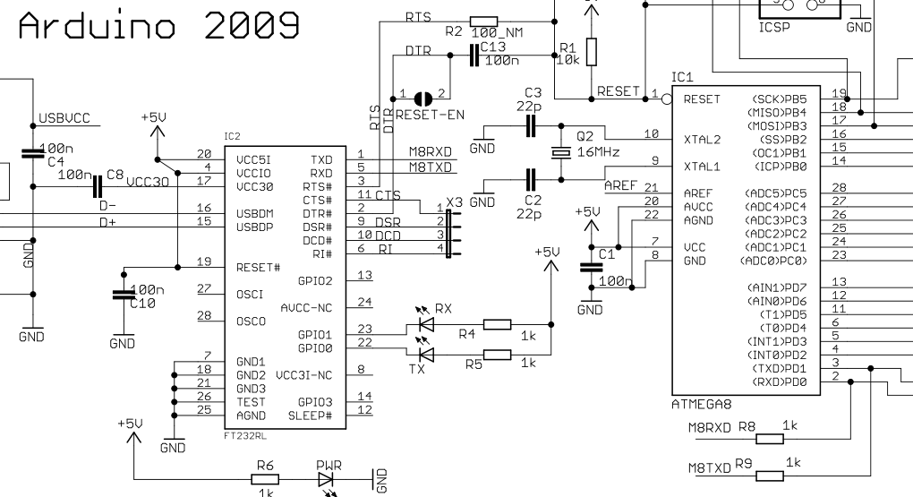
Arduino Software Serial Data Bits Diagram

Normally if you want to send data over you would use the Arduino's built in hardware SPI controller, which is accessible via the SPI.h library. The problem with this is that you are confined to a specific set of pins, and to sending data in multiples of 8 bits. But what if you want to send data over a different set of pins? Or 12 bits of data for example? Or what if your microprocessor doesn't even have an SPI controller?
Arduino - ArduinoBoardUno. Game Of Thrones Season 4 Two Swords. The Arduino software includes a serial monitor which allows simple textual data to be sent to and from the Arduino board.
Block Diagram: Christmas Light Show with Arduino. Software sends out the MIDI data which is received. And select the Arduino port as the serial port and. Begin() Description. Sets the data rate in bits per second (baud) for serial data transmission. For communicating with the computer, use one of these rates. Esp8266 / Arduino. 8 data bits, odd (O), even (E), and no (N). Activex Control For Google Chrome. I've done this also for official ESP8266 Software Serial library.
Is the technique of manually manipulating the microprocessor's pins in software to transmit the data, rather than using a dedicated hardware controller. Although it is a lot efficient than a hardware controller, it is a little more flexible.

To keep things simple, we will be looking at SPI mode 1 only. In this mode, the base value for the clock is 0, and data is captured on the rising edge. Lets take a look at the SPI timing diagram for mode 1. This first thing we need to do, to communicate with a slave, is pull the SS pin low. This is usually done in software anyway, and not by a dedicated controller, so this isn't really part of the bitbanging process. Here are the steps we need to do to bitbang the data: • First we need to set the MOSI (Master Out Slave In) pin to a 1 or a 0, according to the first bit in our data variable. • We then need to set the SCK (Clock) pin high.
This causes the slave to capture the state of the MOSI pin (ie. The first 'bit' of the data) into its own memory. • Next, we read the state of the MISO (Master In Slave Out) pin into the first bit of a new variable. When the transmission is complete, this variable will hold the data sent from the slave to the master. • Now the SCK pin can be set low. • Finally, we repeat this process, moving on to the next bit in the variable each time, for however many bits are in the data variable.